VMC Machine Full Form, Working Principle, Operations, Spindle Speed, Motor and More
CNC machines are available in diverse types and configurations for different purposes. In this article, let’s get into an introduction to the VMC machine, along with its full form, working principle, operations, spindle speed (RPM), motor, and more.
VMC Full Form
VMC stands for Vertical Machining Center. It’s a special kind of machine used for cutting and shaping materials like metal and plastic.
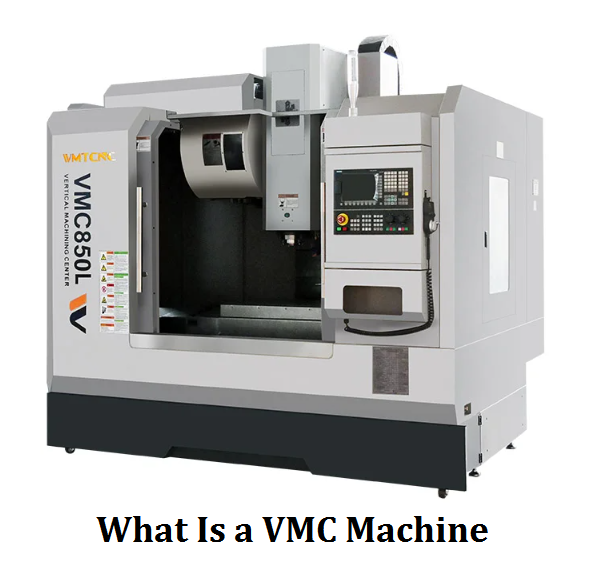
What is a VMC Machine?
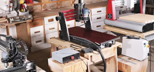
A VMC machine is a type of machining center that uses a vertically positioned spindle to hold and move cutting tools. This means the tools can move up and down to cut materials placed on a table below. VMC machines are controlled by computers (CNC), which helps them make precise shapes and designs automatically.
Vertical machining centers have a worktable that can move in different directions (left, right, forward, and backward) to properly align the material being shaped. They typically include an automatic tool changer that is used to switch tools quickly without stopping. The vertical spindle design offers great visibility for the operator; it is easier to see what’s happening during the cutting process.
One of the biggest advantages of VMC machines is their high precision. They can create very precise parts that fit together perfectly, which is ideal for manufacturing aerospace and automotive components. The vertical machining center can also handle different tasks such as milling, drilling, and tapping, and can work with many materials. Additionally, VMC machines improve efficiency by reducing the need for manual work.
However, there are some downsides. VMC machines can be quite expensive to buy and maintain. They also require skilled operators to program and manage them, so training is necessary. Additionally, while they are great for many tasks, they may not be the best choice for very large or heavy materials due to their design.
How Does a Vertical Machining Center Work?
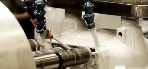
The working principle of a VMC machine is that it operates by using a vertically positioned spindle that holds a cutting tool and spins at high speeds to shape materials. First, the workpiece is securely clamped onto the worktable, which can move in different directions (X, Y, and Z) to align perfectly with the tool. The operator inputs a programmed set of instructions into the CNC control system, which directs how the machine should move and operate. During machining, the spindle rotates the tool while the worktable shifts to allow the tool to cut into the workpiece, removing material to create the desired shape. If multiple tools are needed, the machine can automatically change them as specified in the program. Once the machining is complete, the machine stops, and the operator checks the finished workpiece for accuracy.
Vertical Machining Center vs Horizontal Milling Machine
The main difference between a vertical machining center (VMC) and a horizontal milling machine is how their spindles are positioned. In a VMC, the spindle is vertical, meaning it holds the cutting tool pointing straight down. This helps when cutting shapes and details from above. On the other hand, a horizontal milling machine has its spindle lying flat, which means the cutting tool moves side to side. This design is useful for different types of cutting tasks.
The spindle orientation impacts how they work and what they can do. VMC machines are great for creating complex shapes and three-dimensional designs. They can easily cut flat surfaces and make holes and grooves. But horizontal milling machines are better suited for working on large, flat surfaces and making straight cuts, like slots and keyways. In addition, on a VMC machine, the chips fall down directly, so it is easier to keep the work area clean. However, horizontal machines need extra tools to help remove chips to avoid sticking to the cutting tool and workpiece.
Vertical Machining Center Spindle Speed (RPM)
Spindle speed is how fast the spindle of a Vertical Machining Center (VMC) turns, measured in revolutions per minute (RPM). This speed affects how efficiently the machine can cut and shape materials. A higher spindle speed means the cutting tool can remove material more quickly, which is important when speed and precision are key, like making molds or parts for cars and airplanes. Typically, standard VMC machines operate between 6,000 and 8,000 RPM. High-speed VMCs can go even faster, reaching speeds of 10,000 to 40,000 RPM. For example, when machining softer materials like aluminum, higher speeds are preferred, while harder materials like steel need slower speeds to prevent damage to the cutting tools.
The VMC RPM will influence the surface finish of machined parts. For instance, when machining aluminum, using a high spindle speed (like 10,000 RPM) allows for smoother cuts and better surface quality. In contrast, if the spindle speed is too low (like 2,000 RPM), the surface might end up rough with visible tool marks.
Which Motor is Used in VMC Machines?
A Vertical Machining Center primarily uses two types of motors: mechanical spindles and electric spindles. Mechanical spindles consist of parts like gears and belts that rely on an external motor to turn the spindle. For example, the Fadal VMC TRM model uses a DC motor with a spindle speed of 4,000 RPM. In contrast, electric spindles have a built-in motor that directly drives the spindle, which can adjust speed more smoothly. They do not require extra parts like belts and gears, less energy is wasted, and they are more accurate. Electric spindles are also lighter and can spin faster. However, they can be more complicated to maintain. Mechanical spindles, while bulkier, are simpler and easier to repair, a good choice for tougher materials.
How to Operate a Vertical Machining Center?
Before operating the VMC machine, make sure the worker is properly trained and wear the safety gear like glasses and gloves.
1. Check the machine for any damage and ensure the spindle, worktable, and control panel are clean.
2. Choose the right cutting tools and make sure they are in good condition and securely attached.
3. Secure the workpiece on the worktable with clamps and ensure it is aligned and stable.
4. Use the control panel to define the machine’s zero point and the workpiece’s zero point.
5. Turn on the machine’s power supply and check the control panel status.
6. Switch to manual mode to move the axes (X, Y, Z) using the control panel.
7. Install the selected tools into the spindle, use the tool changer if available.
8. Move the spindle and worktable to bring the tool close to the workpiece, be careful to avoid collisions.
9. Change the machine to automatic mode once the tool is positioned correctly.
10. Enter the machining program into the control system, usually in G-code.
11. Run a simulation to check for errors or potential collisions before actual machining.
12. Begin the machining process once the program is confirmed to be error-free.
13. Watch the machining process to ensure everything is running smoothly and be ready to help if needed.
14. Allow the machine to automatically change tools if the program requires it.
15. The machine will stop automatically once the machining is finished.
16. Move the tool away from the workpiece to a safe position. Turn off the machine’s power supply.
17. Remove the workpiece and tools, and clean the worktable of any chips or debris. Check the finished workpiece to ensure it meets the specifications.