How to Convert a 3-Axis CNC Lathe to 5-Axis Machining?
Here, we are going to introduce several typical cases of process improvement for parts. By using special cutting tools and fixtures, the five-axis CNC machining of the parts is changed to three-axis CNC machining. In practical applications, process improvement methods and solutions are developed based on the structural characteristics of the parts themselves, thereby enhancing the coordination of CNC resources between vehicles, improving production efficiency, and achieving the goal of cost reduction and efficiency improvement.
How to Use 3-Axis CNC Machine for 5-Axis CNC Machining?
Most of the current mechanical manufacturing companies or CNC machining centers have mainstream three-axis CNC machine tools, abundant production resources, and great potential for cluster capacity improvement. In contrast, the number of five axis machine tools is relatively small, and the occupancy rate of five axis CNC machine tools is extremely high. The production capacity is obviously insufficient, and the production bottleneck is large, which hinders the improvement of production efficiency and has become an urgent problem to be solved.
In order to effectively alleviate the production pressure of five axis CNC machine tools, fully leverage the advantages of five axis machine tools, enhance the coordination of CNC production resources, further improve the cluster production capacity of three-axis CNC machine tools, and achieve the goal of cost reduction and efficiency improvement, it is possible to sort out and analyze the CNC part models of some models, find suitable parts for “five axis to three axis” transformation, and alleviate the above difficulties from the perspective of process and scheme optimization, and improve production efficiency. Below, we will list some typical cases of “5-axis parts to 3-axis” to show you how to implement this method to achieve efficient production at low cost.
Case 1. CNC Milling of side walls with small closed angles
The most key point in the improvement of the “3 axis to 5 axis” process plan for a partition component (six in one group) is the milling of the thin-walled sidewall. In addition to leaving sufficient machining allowance for parts during group processing to ensure machining rigidity, special cutting tools should be used to complete the milling of small closed angle (thin-walled inner bending with an angle of about 6 ° with the vertical plane) side walls.
1.1. CNC Part structure and process analysis
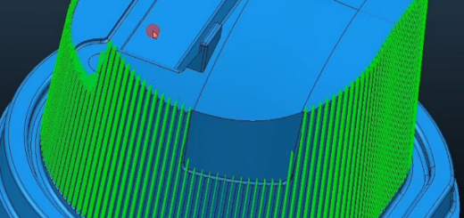
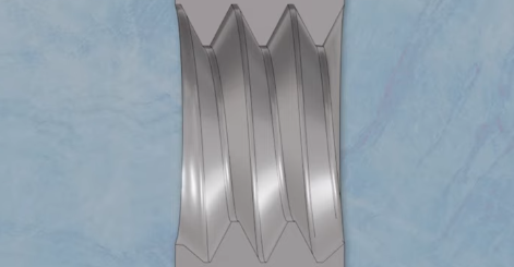
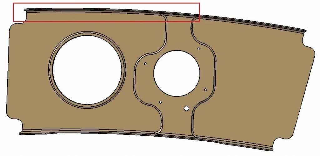
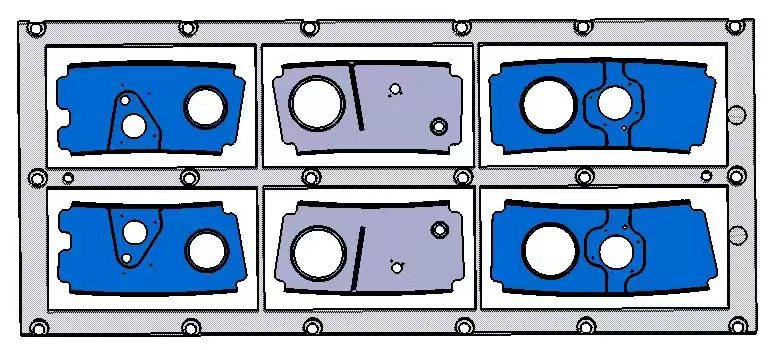
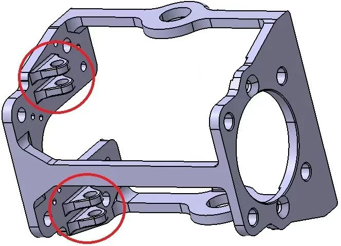
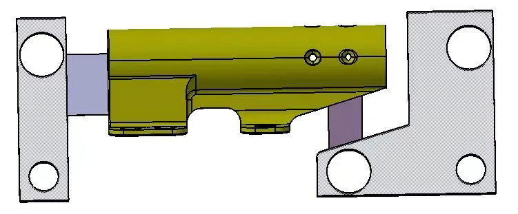
Figure 1 shows a thin-walled partition component made of 7050-T7451- δ 30. with a relatively simple structure. But the wall thickness and web thickness are both 1.5mm, and there is a small closed angle (as shown in Figure 1. the thin wall is bent inward and has an angle of about 6 ° with the vertical plane). The overall size of the component is about 320mm × 180mm, which belongs to the typical thin-walled frame plate type component. The original process plan was five axis CNC machining, but now it has been successfully changed to three-axis CNC machining with a T-shaped knife. The six in one group processing technology for thin-walled partitions is overlapped as shown in Figure 2.
1.2. CNC Milling of small closed angle side walls
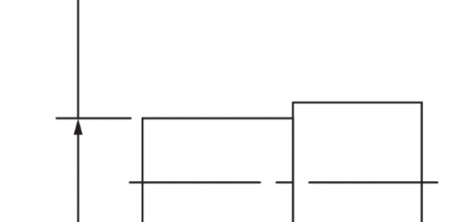
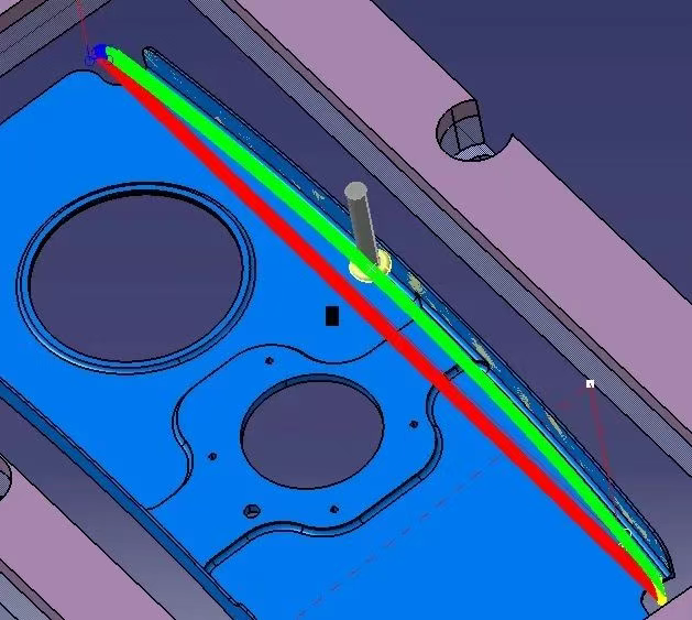
Figure 3 shows the process of milling the inner wall with a T-shaped cutter. For this type of open and closed angle sidewall machining, T-shaped cutters are preferred for milling. It is precisely because the T-shaped cutter is used to mill the small closed angle side wall that the “five axis to three axis” process scheme for the six in one partition part can be applied and implemented. Figure 4 shows the application of T-shaped knives in other characteristic parts.
Case 2. Application of multi-station milling method
In addition to the use of special cutting tools, the application of multi station milling methods in actual production mostly adopts the process arrangement of multi station machining, which decomposes the original five axis CNC machining into single station three-axis CNC machining in the X, Y, and Z directions. There are mainly two situations: one is the multi station swing of the workpiece itself, and the other is the multi station swing of the auxiliary fixture.
2.1. Multi station swing machining of workpieces themselves
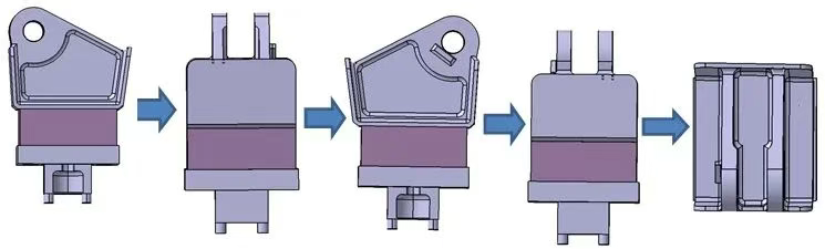
The multi station swing machining mode of the workpiece itself involves milling the workpiece in both forward and reverse directions, combined with a hanging method, to complete up and down milling and achieve overall CNC machining of the part. All milling work is completed on a three-axis CNC machine tool. The following figure shows a certain bracket component, made of 7050-T7451- δ 50 material. The component structure is relatively complex, with curved ear pieces and the entire curved cylinder surface. The end of the cylinder surface requires drilling, making it a typical multi station machining component.
The original five axis process was arranged to complete the front and back docking processing, but now it has been changed to three-axis front and back milling, and combined with the hanging method to complete the upper and lower milling and drilling. The following figure shows the multi station swing milling process flow of the bracket. Based on the feedback from the actual processing situation in the workshop, this swing milling machining method is highly suitable for large-scale three-axis CNC machining. The most significant and beneficial improvement in the production capacity of the company’s three-axis CNC cluster is achieved through customized standard process holes and standard universal matching fixtures.
2.2. Multi station swing machining of auxiliary fixtures
The common tooling modes for multi station swing machining of auxiliary tooling are divided into three types: vertical and horizontal conversion tooling, swing tooling, and fixed angle tooling.
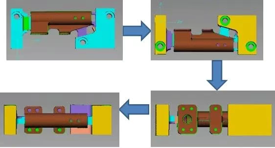
(1) The use of the vertical and horizontal conversion fixture – the incoming raw material of the parts is reversed onto the fixture, and the fixture’s conversion swing is used to achieve one-time clamping and multi station processing of the parts. The alignment origin of the CNC machine tool is always at the center hole position of the fixture surface, which ensures that the machining origin remains unchanged during the machining process. In practical operation, multi station CNC machining of parts can be achieved by manually standing or lying down the fixture. The following figure shows the process flow of the vertical horizontal conversion fixture used for processing a certain joint component.
(2) The use of swing tooling – Swing tooling is commonly used for parts that require swing machining within a range of ± 90 °, and is a non fixed angle tooling. In practical applications, it is necessary to rely on a top pin or turntable for clamping and rotation, and to calibrate the center axis of the fixture to coincide with the center axis of the chuck. The clamping application of swing tooling on a certain rod part, through the rotation of the turntable, realizes the swinging and rotating milling of the rod part within a certain angle, thereby avoiding the need for further processing on a five axis machine tool and avoiding the occupation of five axis machine tool resources.
(3) The use of fixed angle fixtures – Fixed angle fixtures refer to fixtures purchased or self-made based on the characteristics of the part, with the same angle as the milling part, forcing the milling part of the part to be placed vertically or horizontally, thereby achieving three-axis CNC machining of the part. The fixed angle fixture is applied to the 45 ° blind groove machining of a certain joint part. By self-made fixed angle fixtures, the blind groove is placed in a vertical state, making it easier for three-axis machine tools to complete the milling of the blind groove. This truly changes the part from five axis CNC machining to three-axis CNC machining.
Why Turn 3-Axis CNC Machine for 5-Axis Machining?
The “3-axis to 35-axis” process improvement plan for the parts specifically solves the following problems:
- We independently designed, manufactured, and applied multiple sets of fixtures and jigs based on the structural characteristics of different parts, greatly alleviating the production pressure of the company’s five axis CNC machine tools, providing effective solutions, and achieving targeted goals to reduce costs and increase efficiency.
- The successful application experience of different fixtures and process technologies can be extended to process improvement plans for other similar parts.
- By carrying out the “5 axis to 3 axis” process improvement work, the company has successfully initiated its thinking on the issue of “process guidance for production, production feedback process”, breaking the traditional inherent process arrangement and part clamping processing ideas, and providing strong technical support for the company’s development.
The improvement work of the “five axis to three axis” process plan for typical parts focuses on enhancing the production and processing capabilities of the parts from a process perspective, improving workshop production efficiency, and achieving the goal of cost reduction and efficiency improvement. The applied process methods, technical means, auxiliary fixtures, and cutting tools have a reference and guiding role for the process improvement of other parts.