What is Datum in GD&T – GD&T Datum Definition, Symbol, Targets, Reference Frame, Examples
In Geometric Dimensioning and Tolerancing (GD&T), the concept of a datum is central for inspection and part alignment. Datums provide a way to consistently align an imperfect physical part to a perfect reference, enabling accurate measurement and comparison. Let’s walk through the role of datums in GD&T, including their definition, symbols, reference frames, targets, and some practical examples.
What is a Datum in GD&T?
In GD&T, a datum is a theoretically perfect point, axis, or plane that serves as a reference for measuring and manufacturing parts. While actual part features may have imperfections, datums are always considered perfect. The process involves aligning the part to this “perfect world”, a geometric grid defined by the datums, so inspectors can determine how much the real part deviates from the ideal.
When setting up datums, the alignment is always to a perfect reference, even if the actual part surfaces are not. For instance, aligning a surface to a granite table (datum A) controls three degrees of freedom, preventing movement in specific directions and orientations. This approach enables repeatable, reliable inspections.
GD&T Datum Symbols
Datums are identified on engineering drawings using standardized symbols, a rectangular frame containing a letter (A, B, C, etc.), attached to a feature with a leader line or attached directly to a feature control frame. These symbols indicate which surfaces, axes, or points are being used as the reference for measurement. The order in which datums are listed (primary, secondary, tertiary) defines their priority and the sequence in which they are used during part setup.
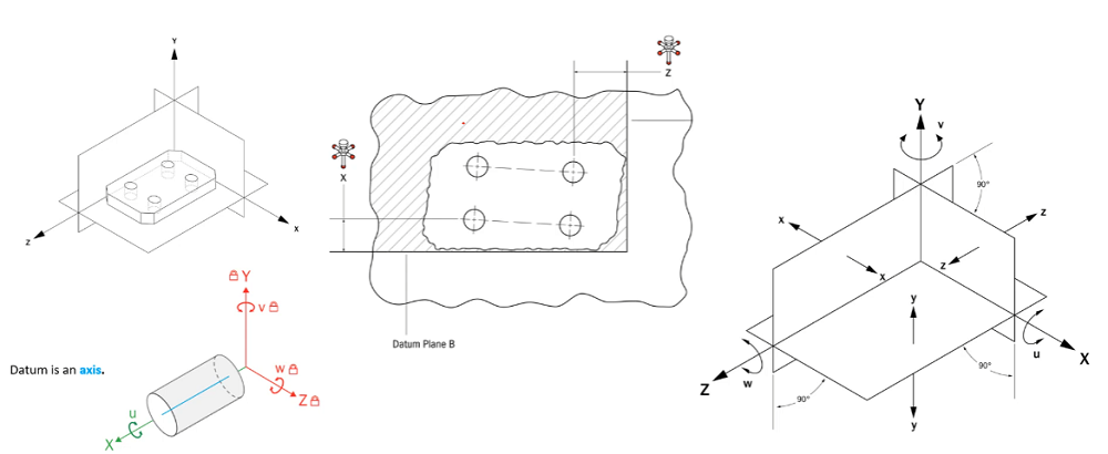
GD&T Compound Datum
Sometimes, a single datum feature is not enough to provide a stable reference. In these cases, a compound datum is used, which may combine multiple features such as two holes or a slot and a surface. For example, two holes can serve as secondary and tertiary datums (datum B and C), providing axes that further constrain the part. The intersection of planes or axes formed by such features becomes the datum, ensuring a stable and repeatable reference for measurement.
GD&T Datum Reference Frame
The datum reference frame is the foundation for all measurements in GD&T. It is established by aligning the part to three mutually perpendicular planes, typically labeled as primary (A), secondary (B), and tertiary (C) datums.
- The primary datum (A) restricts three degrees of freedom by contacting three points on a surface, such as a granite table.
- The secondary datum (B) is always perfectly perpendicular to the primary and restricts two more degrees of freedom by contacting two points.
- The tertiary datum (C) is perpendicular to both the primary and secondary datums and restricts the final degree of freedom with a single point of contact.
This is known as the “3-2-1 rule”: three points of contact for the primary, two for the secondary, and one for the tertiary. By aligning the part to these three planes, all six degrees of freedom (translation and rotation in three axes) are restricted, creating a stable reference for measurement.
GD&T Datum Targets
Datum targets are specific points, lines, or areas on a feature that are used to establish a datum. Rather than using the entire surface, only these marked portions are used to create the reference. For instance, three points on the bottom of a part might be used as datum targets to define the primary datum plane. This approach is especially helpful when surfaces are irregular or too large to use in their entirety.
GD&T Datum Examples
Datums can be established from various features:
- Surfaces: A flat surface can serve as the primary datum (e.g., the bottom of a machined part placed on a granite table).
- Holes: Cylindrical features can be used as datums, with the axis acting as the reference. For example, two holes in a part may be used as secondary and tertiary datums, aligning the axes to the reference frame.
- Compound Features: Sometimes, a combination of features is needed, such as a slot and a hole, to fully constrain the part.
When inspecting a part, the goal is to align it to the datum reference frame so that measurements, such as the position of holes, can be compared to their ideal, basic dimensions given on the drawing. If the measured deviation is within the specified tolerance, the part is accepted; if not, it is rejected.
Datums in GD&T provide the perfect references needed for consistent, accurate part measurement. By establishing a datum reference frame and using the correct symbols and targets, inspectors can align imperfect parts to a perfect grid, ensuring reliable and repeatable results. This systematic approach is the backbone of precise part inspection and quality control in manufacturing.