GD&T Maximum Material Condition (MMC) Definition, Formulas, Design & Uses
Maximum Material Condition (MMC) is an important specification in the design and manufacture of mechanical parts, ensuring that the parts are optimal in terms of function, economy and processability. It provides clear specifications for the size and shape of mechanical parts, ensuring that the parts meet functional requirements while also having the best economy and processability. By deeply understanding and applying the maximum material condition, the design and manufacturing process of the part can be optimized and the overall performance of the product can be improved.
What is GD&T Maximum Material Condition (MMC)
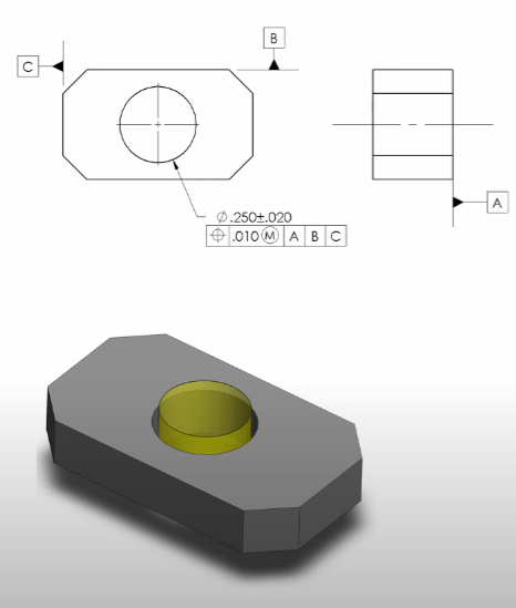
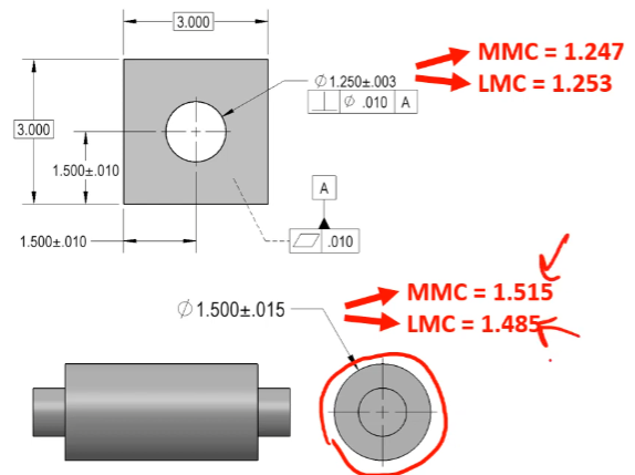
Maximum Material Condition (MMC) is a material condition for a size dimension where the most amount of material exists while still remaining inside the tolerance limits. It is not always simply the largest size allowed for the feature. For external features, MMC is the largest size allowed by the size dimension and its tolerance. For internal features, MMC is the smallest size allowed by the size dimension and its tolerance.
For example, consider a donut-shaped feature:
- For the outside diameter of 5″ ± 1/8″, the MMC is the largest diameter, 5.125″.
- For the inside diameter of 1.5″ ± 1/8″, the MMC is the smallest diameter, 1.375″.
This means for external features like the donut’s outside, growing the size means more material and thus MMC is at the maximum size. For internal features like the donut’s hole, shrinking the size means more material and thus MMC is at the minimum size.
MMC helps to maximize material amount for features of size, ensuring functional fit and assembly compatibility.
Application of Maximum Material Conditions
The application of MMC in design can ensure interference limits and part clearances, ensuring functionality in the worst-case tolerances. In particular, when it is necessary to ensure that two parts do not interfere with each other in the worst-case tolerance range, or to limit the degree of interference between parts, we can use the Maximum Material Condition (MMC). For shafts, the MMC corresponds to the maximum diameter, while for holes, the MMC is the minimum diameter. By ensuring that the MMC of the shaft is always smaller than the MMC of the hole, we can ensure that the clearance between the parts is always maintained.
GD&T Maximum Material Condition (MMC) Formula and Visualization
The virtual condition (VC) formulas help calculate limits for MMC, ensuring proper assembly clearance and tolerance control.
For internal features (holes):
- The virtual condition is the inner boundary, or the smallest hole size the feature can have.
- Formula:
Virtual Condition = MMC size - Geometric Tolerance - Example:
MMC size = 0.230″, geometric tolerance = 0.010″
Virtual Condition = 0.230″ – 0.010″ = 0.220″ - This boundary cannot be crossed, ensuring the pin or fastener will always fit.
For external features (pins):
- The virtual condition is the outer boundary, or the largest pin size plus geometric tolerance.
- Formula:
Virtual Condition = MMC size + Geometric Tolerance - Example:
MMC size = 0.270″, geometric tolerance = 0.010″
Virtual Condition = 0.270″ + 0.010″ = 0.280″ - This imaginary cylinder defines the boundary the pin surface cannot exceed, ensuring assembly fit.
Variable size tolerance is allowed, meaning as the feature size moves away from MMC, more positional tolerance (bonus tolerance) is gained.
GD&T Maximum Material Condition (MMC) Design
Designing to MMC involves understanding Rule #1:
The surface of any regular feature of size cannot extend beyond the envelope of perfect form at MMC.
- For internal features, MMC occurs at the smallest diameter (most material), and LMC (Least Material Condition) at the largest diameter.
- For external features, MMC occurs at the largest diameter (most material), and LMC at the smallest diameter.
This rule controls form to the envelope at MMC, ensuring assembly compatibility. For example, a hole with form error cannot exceed the MMC envelope, or it will fail assembly with a mating pin. The envelope at MMC is the perfect form boundary used for functional assembly checks.
Controlling form to LMC is rare and only applies in special cases, such as when minimum wall thickness is critical, and no mating feature passes through the hole. In such cases, perfect form is controlled at LMC, not MMC.
Wall thickness considerations often require controlling LMC but do not restrict form beyond the LMC envelope.
When To Use MMC?
MMC and MMB modifiers should be used primarily on features of size that have mating features and clearance requirements. Key points include:
- MMC modifier is applied to features of size to allow bonus tolerance as the feature moves away from MMC, increasing clearance and positional tolerance.
- MMB (Maximum Material Boundary) modifier allows datum shift during assembly, simulating how parts fit together when clearances vary.
Use MMC when the mating part is not a press fit and clearance increases as the feature size moves away from MMC.
Example:
- A hole measured at MMC (smallest diameter for internal feature) has no bonus tolerance for position.
- If the hole grows larger (away from MMC), more positional tolerance is allowed because clearance is increased.
MMB is similar but relates to datum features and allows datum shift to simulate part assembly and tolerance stack-up realistically.
MMC and MMB modifiers cannot be applied to features without size elements (such as planar surfaces).