Fanuc G Code and M Code List – What Are G Codes and M Codes in CNC
G-code and M-code are essential languages used in CNC programming for the machining process. Here we’ll explain the basics about them and show the list of the Fanuc G Codes and M Codes.
What is G-Code in CNC?
G-Code is a programming language used to control CNC (Computer Numerical Control) machines by giving precise instructions on tool movements. It tells the machine where to move the cutting tool, how fast to move, and what path to follow to shape a part. Each command starts with the letter “G” followed by numbers that represent specific actions, like rapid positioning (G00), linear cutting at a set speed (G01), or circular movements (G02/G03). These codes include coordinates on X, Y, and Z axes to define exact positions, enabling CNC machines to produce complex shapes with high accuracy and repeatability. G-Code is essential for guiding the geometry of the machining process and transforming digital designs into physical parts.
What is M-Code in CNC?
M-Code controls the miscellaneous or auxiliary functions of a CNC machine that are not related to movement. It handles machine operations like starting or stopping the spindle (M03), turning coolant on or off (M08/M09), or changing tools (M06). Each M-Code begins with the letter “M” followed by a number, and these commands ensure the machine performs essential tasks required for the cutting process but unrelated to the tool’s path. M-Codes can vary between machines and are customized to control non-cutting actions that support the machining operation, making them the organizers of machine functions.
How to Understand and Read G Codes
- Identify the letter “G” followed by a number, which gives a movement command.
- Look for coordinate values (X, Y, Z) that specify the tool’s position in space.
- Note the feed rate (F) indicating how fast the tool moves.
- Observe any additional commands that affect motion, like circular interpolation (G02, G03).
- Break down the code line-by-line, recognizing each part’s function in the sequence.
How to Understand and Read M Codes
- Find the letter “M” followed by a number that instructs a machine function.
- Match the code with its meaning, such as spindle start (M03) or coolant on (M08).
- Remember that M codes usually control non-movement operations.
- Check if the M code is combined with others, ensuring commands do not conflict.
- Learn the machine-specific variations to correctly interpret each M code.
Difference Between G Codes and M Codes
G codes and M codes serve different but complementary roles in CNC programming. G-codes focus on controlling the geometry and movement of the cutting tool, directing exactly where and how to cut the material. In contrast, M codes manage the machine’s auxiliary functions that support the cutting process, such as turning the spindle on or off, activating coolant, or changing tools. While G codes command the tool’s path and speed during machining, M codes handle the machine’s operational tasks that are not directly related to tool movement. Together, they enable a CNC machine to work smoothly and efficiently, producing precise parts with coordinated actions.
What Is CNC Programming Language?
CNC programming is the process of writing instructions that tell computer numerical control (CNC) machines how to perform precise manufacturing tasks like cutting, milling, drilling, or shaping materials. These instructions are usually written in a special language called G-code, which acts as the machine’s language, guiding tool movements, spindle speeds, feed rates, and tool changes. CNC programming can be done manually by writing G-code by hand, but nowadays most programmers use CAD (Computer-Aided Design) and CAM (Computer-Aided Manufacturing) software to create 3D models and automatically generate the necessary G-code. This code is organized in blocks, with each block representing a specific step in the machining process, making it easier to read, modify, and troubleshoot. Understanding CNC programming and its language is important for operators and programmers to ensure smooth, accurate, and efficient production.
What Machines Use G-Code?
1. CNC Milling Machines:
CNC milling machines use rotary cutting tools that spin to remove material from a stationary workpiece. These machines can perform many types of milling processes, like face milling or contouring. They use G-code to direct the tool’s path precisely in multiple axes, shaping complex 3D parts.
2. CNC Turning Machines:
Also called CNC lathes, turning machines hold the workpiece and rotate it while a stationary cutting tool shapes the outside surface. G-code controls the tool’s movements, enabling the machine to create symmetrical cylindrical or conical shapes with great precision, commonly used for shafts, bolts, and similar parts.
3. CNC Grinding Machines:
Grinding machines use an abrasive wheel to smooth or finish a surface by removing very small amounts of material. They often work after milling or turning to improve surface quality. G-code guides the grinding wheel’s movements to achieve accurate and smooth finishes.
4. CNC Drilling Machines:
These machines drill holes into a workpiece using a rotating drill bit. G-code programs the drilling locations, depths, and speeds. Drilling CNC machines are often used to create holes for screws, fixtures, or assembly. For larger holes, CNC boring machines are employed.
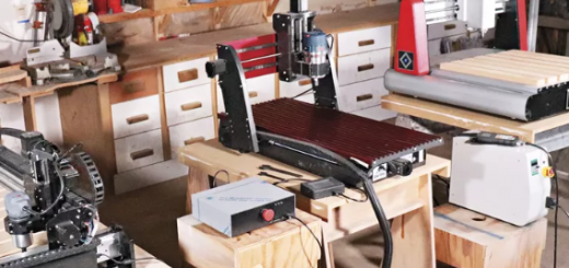
5. CNC Routing Machines:
CNC routers combine a CNC system with a handheld-style router to cut and carve materials like wood, plastic, or soft metals. They can create detailed patterns or shapes by precisely controlling the router via G-code commands.
6. CNC Laser Cutting Machines:
Laser cutters use a powerful, focused laser beam to melt or vaporize material, cutting it with high precision. G-code directs the laser’s path, but laser cutting is limited to materials that won’t damage the optics, as some plastics release harmful gases when cut.
7. CNC Water Jet Cutting Machines:
Water jet cutters use a fine, high-pressure water stream to cut through materials, including very thick or hard metals. G-code controls the movement of the water jet cutting head, allowing intricate shapes to be cut without heat that could damage the material.
Fanuc G-Code List (Lathe)
| G code | Description |
|---|---|
| G00 | Rapid traverse |
| G01 | Linear interpolation |
| G02 | Circular interpolation CW |
| G03 | Circular interpolation CCW |
| G04 | Dwell |
| G09 | Exact stop |
| G10 | Programmable data input |
| G20 | Input in inch |
| G21 | Input in mm |
| G22 | Stored stroke check function on |
| G23 | Stored stroke check function off |
| G27 | Reference position return check |
| G28 | Return to reference position |
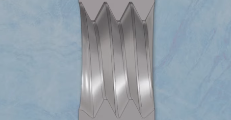
| G32 | Thread cutting |
| G40 | Tool nose radius compensation cancel |
| G41 | Tool nose radius compensation left |
| G42 | Tool nose radius compensation right |
| G70 | Finish machining cycle |
| G71 | Turning cycle |
| G72 | Facing cycle |
| G73 | Pattern repeating cycle |
| G74 | Peck drilling cycle |
| G75 | Grooving cycle |
| G76 | Threading cycle |
| G92 | Coordinate system setting or max. spindle speed setting |
| G94 | Feed Per Minute |
| G95 | Feed Per Revolution |
| G96 | Constant surface speed control |
| G97 | Constant surface speed control cancel |
Fanuc G-Code List (Mill)
| G code | Description |
|---|---|
| G00 | Rapid traverse |
| G01 | Linear interpolation |
| G02 | Circular interpolation CW |
| G03 | Circular interpolation CCW |
| G04 | Dwell |
| G17 | X Y plane selection |
| G18 | Z X plane selection |
| G19 | Y Z plane selection |
| G28 | Return to reference position |
| G30 | 2nd, 3rd and 4th reference position return |
| G40 | Cutter compensation cancel |
| G41 | Cutter compensation left |
| G42 | Cutter compensation right |
| G43 | Tool length compensation + direction |
| G44 | Tool length compensation – direction |
| G49 | Tool length compensation cancel |
| G53 | Machine coordinate system selection |
| G54 | Workpiece coordinate system 1 selection |
| G55 | Workpiece coordinate system 2 selection |
| G56 | Workpiece coordinate system 3 selection |
| G57 | Workpiece coordinate system 4 selection |
| G58 | Workpiece coordinate system 5 selection |
| G59 | Workpiece coordinate system 6 selection |
| G68 | Coordinate rotation |
| G69 | Coordinate rotation cancel |
| G73 | Peck drilling cycle |
| G74 | Left-spiral cutting circle |
| G76 | Fine boring cycle |
| G80 | Canned cycle cancel |
| G81 | Drilling cycle, spot boring cycle |
| G82 | Drilling cycle or counter boring cycle |
| G83 | Peck drilling cycle |
| G84 | Tapping cycle |
| G85 | Boring cycle |
| G86 | Boring cycle |
| G87 | Back boring cycle |
| G88 | Boring cycle |
| G89 | Boring cycle |
| G90 | Absolute command |
| G91 | Increment command |
| G92 | Setting for work coordinate system or clamp at maximum spindle speed |
| G98 | Return to initial point in canned cycle |
| G99 | Return to R point in canned cycle |
Fanuc M-Code List (Lathe)
| M code | Description |
|---|---|
| M00 | Program stop |
| M01 | Optional program stop |
| M02 | End of program |
| M03 | Spindle start forward CW |
| M04 | Spindle start reverse CCW |
| M05 | Spindle stop |
| M08 | Coolant on |
| M09 | Coolant off |
| M29 | Rigid tap mode |
| M30 | End of program reset |
| M40 | Spindle gear at middle |
| M41 | Low Gear Select |
| M42 | High Gear Select |
| M68 | Hydraulic chuck close |
| M69 | Hydraulic chuck open |
| M78 | Tailstock advancing |
| M79 | Tailstock reversing |
| M94 | Mirrorimage cancel |
| M95 | Mirrorimage of X axis |
| M98 | Subprogram call |
| M99 | End of subprogram |
Fanuc M-Code List (Mill)
| M code | Description |
|---|---|
| M00 | Program stop |
| M01 | Optional program stop |
| M02 | End of program |
| M03 | Spindle start forward CW |
| M04 | Spindle start reverse CCW |
| M05 | Spindle stop |
| M06 | Tool change |
| M07 | Coolant ON – Mist coolant/Coolant thru spindle |
| M08 | Coolant ON – Flood coolant |
| M09 | Coolant OFF |
| M19 | Spindle orientation |
| M28 | Return to origin |
| M29 | Rigid tap |
| M30 | End of program (Reset) |
| M41 | Low gear select |
| M42 | High gear select |
| M94 | Cancel mirrorimage |
| M95 | Mirrorimage of X axis |
| M96 | Mirrorimage of Y axis |
| M98 | Subprogram call |
| M99 | End of subprogram |