GD&T Concentricity Definition, Symbol, Removal, Standard, Measurement & Concentricity vs Runout
Geometric Dimensioning and Tolerancing (GD&T) is a critical system for defining and communicating part specifications in engineering and manufacturing. Concentricity is one of the main tolerances in GD&T. This guide breaks down everything you need to know about GD&T concentricity, from its basic definition to its alternatives, standard, measurement methods, and how it differs from similar GD&T controls.
What Is Concentricity in GD&T?
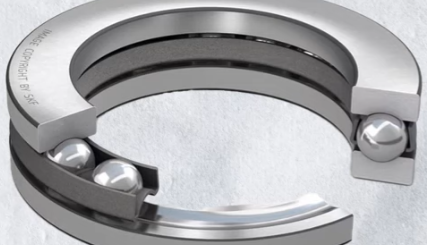
Concentricity, also called coaxiality in the ISO standard, is a 3-dimensional GD&T tolerance that ensures the central derived median points of a cylindrical feature align with a datum axis. Unlike controls that focus on surface or axis alignment, concentricity relies on “derived median points”—the midpoints between pairs of diametrically opposite surface points on a cylindrical feature. For a part to meet concentricity requirements, all these median points (when connected along the feature’s length to form a median axis) must lie within a specified cylindrical tolerance zone centered on the datum axis. Its core purpose is to ensure uniform mass distribution around an axis, which is crucial for parts that spin at high speeds (like transmission gears or ball bearings) to prevent oscillation, uneven wear, or structural failure. Even if a cylindrical feature has surface imperfections (like small dips or notches), it can still be concentric as long as its median points stay within the tolerance zone. This focus on median points makes concentricity unique—but also more complex to measure than other GD&T controls.
Concentricity Symbol
The concentricity symbol in GD&T is a simple yet distinct mark: two small concentric circles (◎). This symbol is placed in the first block of a Feature Control Frame (FCF), which is the standardized way to communicate GD&T tolerances on engineering drawings. The FCF connects to the feature being controlled via a leader arrow, and the full frame includes three key blocks: the geometric characteristic block (holding the concentricity symbol), the feature tolerance block (specifying the diameter of the cylindrical tolerance zone), and the datum block (identifying the reference axis). For example, an FCF with “◎ ⌀0.03 A” means: “Relative to datum axis A, all median points of the controlled cylindrical surface must lie within a cylindrical tolerance zone with a 0.03 diameter.” It’s important to note that material modifiers like Maximum Material Condition (MMC) or Least Material Condition (LMC) are not applicable with concentricity in ASME standards (though ISO allows MMC), as they would introduce variable tolerance zones that conflict with concentricity’s precise mass-balance goal.

Why Was Concentricity Removed from GD&T?
Concentricity was officially removed from the 2018 revision of the ASME Y14.5 GD&T standard, the primary GD&T standard used in the United States, due to two key issues: measurement complexity and limited practicality. Unlike simpler tolerances (like runout or position) that can be measured with basic tools, concentricity requires precise calculation of derived median points—an abstract concept that can only be reliably measured with advanced equipment like Coordinate Measuring Machines (CMMs). This made inspections time-consuming, costly, and prone to error in real-world manufacturing settings. Additionally, concentricity was often misused to control coaxiality (the alignment of two axes), a task that other tolerances perform more effectively and simply. Even in previous ASME versions (like 2009 or 1994), the standard recommended using position, circular runout, or total runout instead of concentricity whenever possible. However, concentricity is not “obsolete” globally—it remains valid in ISO standards (like ISO 1101) and is still enforced on legacy drawings created under pre-2018 ASME standards, as many companies continue to use these older revisions.
What Is the ISO Standard for Concentricity?
The primary ISO standard governing concentricity is ISO 1101, which covers geometric tolerancing for technical drawings and specifications. Unlike the 2018 ASME standard, ISO 1101 retains concentricity as a valid tolerance and uses the same symbol (two concentric circles) to represent both “concentricity” and “coaxiality”—terms that are often used interchangeably in ISO contexts. ISO 1101 defines concentricity as a tolerance that controls the derived median points of a cylindrical feature relative to a datum axis, with a 3-dimensional cylindrical tolerance zone (just like the ASME definition). A key difference from ASME is that ISO 1101 allows the use of Material Modifiers (like MMC) with concentricity, which can expand the tolerance zone based on the feature’s actual size—something ASME never permitted. ISO 1101 is widely used in Europe, Asia, and many global industries, so concentricity remains a common specification in international manufacturing. For precise applications, engineers should reference the latest version of ISO 1101 to understand nuanced requirements, such as how to apply datums or calculate tolerance zones for complex parts.
What to Use Instead of Concentricity?
Due to concentricity’s removal from ASME Y14.5-2018 and its measurement challenges, the standard recommends three primary replacements, depending on the application: position tolerance, circular runout, and total runout. Position tolerance (symbol: ⌖) is the most versatile substitute—it controls the axis of a coaxial feature (instead of median points) within a cylindrical tolerance zone centered on a datum axis. For example, “⌖ ⌀0.1 A” ensures a feature’s axis stays within a 0.1-diameter zone relative to datum A, effectively controlling alignment without median point measurements. Circular runout (symbol: ⟳) is ideal for parts that spin, as it combines control of circularity and concentricity—measured by rotating the part and checking surface variation with a dial indicator, no CMM required. If the part is perfectly round, runout measurements directly reflect concentricity. Total runout (a variation of runout) controls the entire length of a feature, making it great for long shafts or tubes. These alternatives are easier to measure, more cost-effective, and less prone to misinterpretation than concentricity. The only time concentricity is still preferred is for specialized applications requiring strict mass balance (like medical tubing or high-pressure pipes), where median point control is critical.
How to Measure Concentricity in GD&T?
Step 1: Secure the part and establish the datum axis
First, the part must be clamped in a stable position (using fixtures like V-blocks or chucks) to lock all degrees of freedom—this ensures no movement during measurement, which would skew results. Next, you need to define the datum axis (the reference axis for the tolerance zone). For shafts, the datum axis is typically derived from the bearing end (the part that will rotate in the final assembly), as this is the “fixed” point for alignment. On a CMM (the only reliable tool for this measurement), the datum axis is calculated by scanning a datum feature (like a precision cylindrical section) and averaging its surface points to create a theoretical axis.
Step 2: Calculate the center point of one cross-section
For the cylindrical feature being checked, select a cross-section (a circular slice perpendicular to the datum axis). Using the CMM stylus, measure at least three pairs of diametrically opposed surface points (points directly across the circle from each other). For each pair, find the midpoint—this is a “derived median point.” Since surface imperfections may cause these midpoints to vary, take the average of the three median points to get the true center point of that cross-section.
Step 3: Repeat for multiple cross-sections along the feature
Concentricity applies to the entire length of the feature, so you need to repeat the cross-section measurement process at several points (the number depends on the feature’s length—longer features require more cross-sections). For example, a 10cm shaft might need cross-sections every 2cm. Once you have the center point of each cross-section, connect these points to form the “measured median axis” of the feature—this axis represents the actual alignment of the feature’s median points.
Step 4: Verify the measured axis lies within the tolerance zone
The final step is to compare the measured median axis to the specified tolerance zone. The tolerance zone is a cylinder centered on the datum axis, with a diameter equal to the tolerance value from the FCF. Using the CMM’s software, check if every point on the measured median axis falls inside this cylindrical zone. If all points are within the zone, the part passes the concentricity requirement; if any point is outside, it fails. This step requires precise software calculations, as the tolerance zone is 3-dimensional and cannot be visually inspected.
Difference Between Runout And Concentricity
1. Core Definition and Measurement Focus
Concentricity is a 3D tolerance that controls the derived median points of a cylindrical feature relative to a datum axis—it focuses on abstract midpoints, not the surface itself. Measuring it requires calculating median points and using a CMM, making it complex and time-consuming. Runout (including circular and total runout) is a simpler 2D or 3D tolerance that measures surface variation as the part rotates around the datum axis. It uses basic tools like dial indicators or V-blocks, where the indicator reads how much the surface moves during a full 360° rotation. Runout doesn’t care about median points—it directly checks how “wobbly” the part is when spinning.
2. What They Control (Single vs. Combined Attributes)
Concentricity is a “single-attribute” control: it only ensures median points align with the datum axis, not the feature’s roundness. A part can be oval (poor circularity) but still concentric if its median points are centered. Runout, by contrast, is a “combined-attribute” control: it simultaneously checks both concentricity and circularity. For example, if a part is perfectly round (ideal circularity), its runout measurement will equal its concentricity value. If the part is off-center (poor concentricity) but round, runout will reflect that offset. This combination makes runout more useful for most rotating parts, as it addresses both alignment and shape issues.
3. Practicality and Cost
Concentricity is impractical for high-volume manufacturing due to its reliance on CMMs, which are slow and expensive. It also requires highly skilled inspectors to avoid measurement errors. Runout, however, is fast and low-cost—inspections can be done in under 10 seconds with a dial indicator, making it suitable for production lines. This practicality is why ASME recommends runout over concentricity for most applications. For example, a automotive shaft can be checked for runout on the assembly line, whereas concentricity would require sending samples to a lab for CMM testing.
Difference Between Cylindricity And Concentricity
1. Control Purpose: Shape vs. Alignment
Cylindricity is a “form tolerance” that controls the overall shape of a cylindrical feature—it ensures the feature is perfectly round and straight along its entire length. It defines a tolerance zone as two coaxial cylinders (inner and outer), and every surface point of the feature must lie between these cylinders. Cylindricity doesn’t need a datum (it’s independent) because it only cares about the feature’s own shape, not its alignment to another part. Concentricity, by contrast, is an “orientation/location tolerance” that controls alignment to a datum axis—it ensures the feature’s median points are centered on the datum, not that the feature itself is perfectly shaped. A part can have poor cylindricity (e.g., a slightly bent shaft) but still be concentric if its median points align with the datum.
2. Tolerance Zone Type and Reference
Cylindricity’s tolerance zone is two coaxial cylinders (the gap between them is the tolerance value), and it has no reference to a datum—this zone is based solely on the feature’s ideal shape. Concentricity’s tolerance zone is a single cylindrical zone centered on a specific datum axis—its position is tied directly to the datum, not the feature’s own shape. For example, a cylindricity tolerance of 0.02 means the feature’s surface must stay between two cylinders 0.02 apart, regardless of where the feature is located. A concentricity tolerance of 0.02 means the feature’s median axis must stay within a 0.02-diameter cylinder centered on datum A.
3. Applications and Complementarity
Cylindricity is used for parts where smooth, uniform shape is critical—like hydraulic rams (to prevent leaks) or bearing races (to ensure even wear). It solves problems like “wobble” caused by a bent or uneven surface. Concentricity is used for parts where mass balance around a datum is critical—like high-speed gears (to avoid oscillation) or medical tubing (to ensure uniform wall thickness). These tolerances often work together: a shaft might use cylindricity to ensure it’s straight and round, plus concentricity to ensure it aligns with the engine’s datum axis. However, cylindricity can’t replace concentricity (it doesn’t control alignment) and vice versa (concentricity doesn’t control shape).