Different Types of Lathe Machine Operations (Principle, Tools, Uses & FAQs)
A lathe machine is a versatile machine tool that can complete various manufacturing processes, this article will explain each lathe machine operation along with its working principles, cutting tools and common uses. Also, we’ll get into some frequently asked questions about lathe machine and its operations.
Different Types of Lathe Machine Operations
1. Straight Turning
Straight turning is the most common lathe operation. It features the removal of material from the outer surface of a rotating workpiece to reduce its diameter evenly, producing a smooth cylindrical shape. The cutting tool moves parallel to the axis of the spinning workpiece, shaving off thin layers of material. This operation is essential for shaping shafts, rods, and pins with uniform diameters.
Tools:
- Single-point cutting tool (high-speed steel or carbide)
- Lathe chuck or centers for workpiece holding
Applications:
- Manufacturing machine shafts
- Producing metal rods and pins
- Creating cylindrical parts for automotive and machinery components
2. Taper Turning
Taper turning creates a conical surface by gradually reducing the diameter of the workpiece along its length. The cutting tool moves at an angle to the axis of rotation, either by swiveling the compound rest or offsetting the tailstock. This produces parts with a taper, such as tool holders or tapered shafts, which fit into matching components.
Tools:
- Single-point cutting tool with appropriate rake and relief angles
- Compound rest or adjustable tailstock
Applications:
- Tool holders and machine tapers
- Tapered pins and shafts used in machinery assemblies
3. Contour Turning
Contour turning shapes the workpiece into complex curved profiles rather than simple straight or tapered shapes. The cutting tool follows a predefined path, controlled manually or by CNC programming, to form irregular or decorative curves. This operation is useful for making cams, pulleys with grooves, or ornamental parts.
Tools:
- Single-point cutting tools
- CNC lathe or skilled manual setup for tool guidance
Applications:
- Camshafts
- Decorative machine parts
- Custom curved profiles for special machinery
4. Step Turning
Step turning produces a workpiece with distinct diameter sections separated by clear steps or shoulders. The cutting tool removes material at different depths along the length, creating a stepped profile. This operation is important for parts like stepped shafts or pins that require multiple diameter changes.
Tools:
- Single-point cutting tool
- Lathe chuck or centers
Applications:
- Stepped shafts in engines or gearboxes
- Multi-diameter pins and connectors
5. Chamfer Turning
Chamfer turning removes sharp edges by cutting a small angled surface at the corner of the workpiece. This beveled edge improves the safety of handling parts and prepares them for fitting or assembly. The tool is fed at an angle to the rotating workpiece, creating a smooth chamfer.
Tools:
- Single-point cutting tool set at the desired angle
Applications:
- Removing burrs and sharp edges
- Preparing parts for welding or assembly
- Improving the aesthetics and safety of finished parts
6. Form Turning
Form turning uses a specially shaped cutting tool that matches the desired profile. The tool presses against the rotating workpiece to transfer its shape in one pass, producing complex profiles quickly. This operation is often used for decorative or functional shapes like grooves or ridges.
Tools:
- Formed a single-point cutting tool with a specific profile
Applications:
- Decorative patterns on metal parts
- Functional profiles such as gear teeth or ridges
7. Facing
Facing cuts the end surface of a rotating workpiece to create a flat face perpendicular to its axis. The tool moves radially from the center to the edge of the workpiece, removing material to prepare the end for further machining or assembly.
Tools:
- Facing tool (single-point cutter)
Applications:
- Creating flat end surfaces on shafts or rods
- Ensuring parts seat properly during assembly
8. Drilling
Drilling on a lathe involves using a drill bit mounted in the tailstock to create holes along the axis of a rotating workpiece. The drill bit feeds into the workpiece while it spins, cutting a round hole.
Tools:
- Drill bits of various sizes
- Tailstock or drill chuck
Applications:
- Making holes for pins, bolts, or fasteners
- Preparing parts for further machining operations
9. Boring
Boring enlarges an existing hole or improves its finish by cutting the interior surface. A boring tool is fed into the hole while the workpiece rotates, removing a small amount of material to increase diameter and improve accuracy.
Tools:
- Boring bar with single-point cutting tip
Applications:
- Enlarging holes for bearings or bushings
- Correcting hole alignment and size in engine blocks or housings
10. Parting (Cutting Off)
Parting uses a narrow blade tool to cut through the rotating workpiece and separate a finished part from the stock material. The tool is fed perpendicularly into the workpiece until it slices through.
Tools:
- Parting tool (thin blade)
Applications:
- Cutting off completed parts
- Trimming excess stock or scrap
11. Threading
Threading cuts helical grooves on the outer or inner surface of a workpiece to make screw threads. The cutting tool moves along the workpiece at a feed rate synchronized with the rotation speed to produce the correct thread pitch.
Tools:
- Threading tool (single-point cutter with sharp profile)
Applications:
- Producing bolts, nuts, screws
- Threaded shafts and fittings
12. Knurling
Knurling presses a serrated or cross-hatched pattern onto the surface of a rotating workpiece using rollers. This creates a textured grip on handles, knobs, or tool parts.
Tools:
- Knurling tool with toothed rollers
Applications:
- Grip surfaces for hand tools
- Decorative patterns on knobs and handles
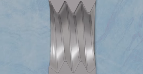
13. Grooving
Grooving cuts narrow channels or slots on the external or face surface of the workpiece. The cutting tool feeds radially into the workpiece to create grooves for seals, rings, or other purposes.
Tools:
- Grooving tool (thin, sharp cutter)
Applications:
- O-ring seats
- Oil grooves on shafts or pistons
14. Reaming
Reaming finishes and sizes a pre-drilled hole to a precise diameter with a smooth surface. The reamer tool is pushed or rotated inside the hole to remove a small amount of material and improve accuracy.
Tools:
- Reamer tool with multiple cutting edges
Applications:
- Precision hole finishing in aerospace or medical parts
- Ensuring tight fits for bearings or pins
How Does a Turning Operation Work?
Turning removes material from a rotating workpiece using a sharp cutting tool. First, the workpiece is fixed in the chuck or between centers and spun at a set speed. The cutting tool is held firmly and moved slowly along the workpiece’s length while pressing into it. The tool slices off thin layers of metal, creating a smooth, round shape. The process uses specific speeds, feeds, and depth to control the finish and size. Coolant may be applied to keep the tool from overheating. The goal is to reach the exact diameter and surface needed by removing material carefully.
Difference Between Boring and Reaming
- Purpose: Boring enlarges or corrects the size and alignment of an existing hole. It can fix shape problems and adjust the diameter roughly. Reaming, however, is used after drilling or boring to make a hole very precisely in size and very smooth inside.
- Precision: Boring offers medium accuracy with tolerances around ±0.05 to 0.1 mm. Reaming is much more precise, with tolerances as tight as ±0.005 to 0.02 mm.
- Surface Finish: The surface from boring is fairly smooth but not very fine. Reaming produces a very smooth, polished hole surface.
- Tools: Boring uses a single cutting edge attached to a boring bar. Reaming uses multi-edged tools called reamers that cut gently.
- Material Removal: Boring removes more material to enlarge holes. Reaming removes just a tiny amount to finish the hole.
- Application: Boring is used when holes need to be bigger or better aligned. Reaming is used when holes need an exact size and excellent finish.
- Hole Path: Boring can correct hole alignment and slightly change the hole path. Reaming does not change the hole’s position or path.
- Tool Adjustment: Boring tools can be adjusted to change their diameter. Reamers have fixed diameters.
- Process Order: Boring usually comes after drilling. Reaming is done after drilling or boring.
- Cost and Efficiency: Boring is cheaper and faster but less precise. Reaming costs more but gives better accuracy and finish.
- Industry Use: Boring is common in automotive and heavy industry. Reaming is important in aerospace, medical, and precision tool making.
What Is the Main Purpose of a Lathe?
The main purpose of a lathe is to shape a rotating workpiece by removing material. It changes the size and surface of round objects like rods or bars by cutting away metal (or other materials). The lathe spins the workpiece while a cutting tool moves to cut it precisely. This creates parts like shafts, pins, screws, and pulleys with exact sizes and smooth surfaces. The lathe helps produce many mechanical parts needed in machines and tools.
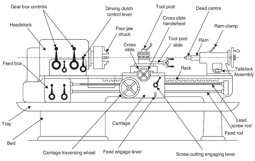
What Are the Main Parts of a Lathe Machine?
- Bed: This is the heavy base of the lathe. It supports all parts and keeps everything aligned. The bed is a flat surface where other parts slide.
- Headstock: Located on the left, it holds the main spindle and controls the rotation speed. It provides power to spin the workpiece.
- Tailstock: Opposite the headstock, it can slide along the bed. It supports the other end of long workpieces or holds tools like drills.
- Carriage: This moves along the bed carrying the cutting tool. It includes the saddle (base), cross-slide (moves tool sideways), compound rest (for angled cuts), and tool post (holds the tool).
- Lead Screw and Feed Rod: The lead screw moves the carriage precisely during threading. The feed rod powers automatic tool movement for turning and facing.
- Apron: The front part of the carriage containing controls for manual or power feed, gear mechanisms, and thread cutting.
- Chuck: The chuck grips round workpieces.
- Spindle and Spindle Nose: The spindle spins the workpiece and has a nose to attach chucks or faceplates.
- Gearbox: Allows changing speeds and feed rates by shifting gears easily.
- Legs: Supports the bed and collects chips and coolant.