Shaft Torsion (Torque) and Angle of Twist Equation Formula & Calculation
When designing or analyzing rotating shafts in mechanical systems, understanding the effects of torsion and calculating the resulting torque and angle of twist is fundamental. These calculations help in ensuring shaft safety, durability, and performance under real-world operating conditions. This guide explains the concepts and formulas for shaft torsion, torque, and angle of twist, and demonstrates how to apply them in practical situations.
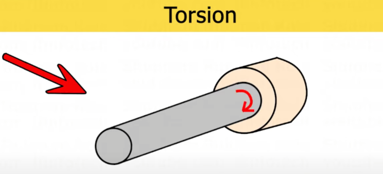
What is Torsion or Torque?
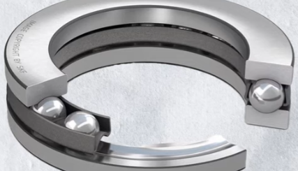
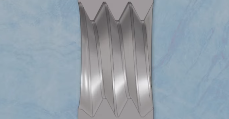
Torsion occurs when a shaft is subjected to rotational forces, causing it to twist about its longitudinal axis. In mechanical applications, a shaft rotates inside a bearing. When one end of the shaft is subjected to a force attempting to rotate it, and the bearing at the other end resists this motion, a twisting action is produced. This twisting is known as torsion, and the moment that causes this action is called torque.
The torque (T) applied to a shaft is calculated by multiplying the tangential force by the radius of the shaft. This relationship is crucial for determining how much force is being transmitted through the shaft and is the starting point for further torsional analysis.
What is Angle of Twist?
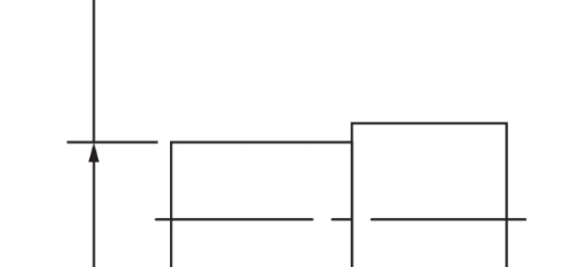
The angle of twist, denoted as θ (theta), measures how much a particular point on the shaft rotates from its original position due to the applied torque. Imagine a point D on the shaft; as torque is applied, this point moves to a new position, D’. The angle formed at the shaft’s center between these two positions is the angle of twist.
For calculations, the angle of twist is typically expressed in radians. For reference, one degree is equal to π/180 radians. The angle of twist is generally uniform along the shaft’s length if the torque and shaft properties remain constant.
Torsion Equation Formula
The torsion in a shaft is governed by a fundamental equation that relates torque, shear stress, and the shaft’s geometry and material properties. The general torsion equation is:
T / Ip = Fs / R = Gθ / L
Where:
- T is the applied torque (or twisting moment)
- Ip is the polar moment of inertia of the shaft’s cross-section
- Fs is the maximum shear stress
- R is the shaft’s outer radius
- G is the modulus of rigidity of the material
- θ is the angle of twist (in radians)
- L is the length of the shaft
This equation provides the foundation for analyzing shaft strength and rigidity under torsional loads.
Angle of Twist Formula
Angle of twist can be determined using the torsion equation, specifically focusing on the relationship between torque, modulus of rigidity, shaft geometry, and length:
θ = (T × L) / (G × Ip)
Where:
- θ is the angle of twist in radians
- T is the applied torque
- L is the shaft length
- G is the modulus of rigidity
- Ip is the polar moment of inertia
This formula helps in predicting how far a shaft will rotate under a given load, which is vital for designing mechanical systems where precise angular displacement is required.
How To Calculate Torque and Angle of Twist in Shaft?
1. Calculating Torque for Solid and Hollow Shafts
- For a solid circular shaft, the maximum torque is found using the formula:
T_max = (π / 16) × Fs × D³
Here, Fs is the permissible shear stress and D is the diameter. - For a hollow shaft, the formula becomes:
T_max = (π / 16) × Fs × (D⁴ – d⁴) / D
Where D is the outer diameter and d is the inner diameter.
2. Calculating Power Transmitted by a Shaft
- The power (P) transmitted by a rotating shaft is calculated as:
P = (2 × π × N × T_mean) / 60
Where N is the speed in RPM and T_mean is the mean torque.
3. Practical Example Calculations
- Given a solid circular shaft of 50 mm diameter rotating at 100 RPM with a permissible shear stress of 75 MPa, the maximum torque induced can be calculated as 1840.776 kN·mm.
- For a solid shaft tasked to transmit a torque of 15 × 10⁶ N·mm, and not exceed 45 N/mm² shear stress, the required shaft diameter is calculated as 119.29 mm.
- If a 30 mm diameter shaft is subjected to 0.25 kN·m torque causing a 3.74° twist over 2 meters, the modulus of rigidity (G) can be determined using the formula and is found to be 0.96 × 10⁵ N/mm².
4. Angle of Twist Calculations
- To find the length of an 8 mm diameter aluminum wire that can be twisted through one revolution without exceeding 45 MPa shear stress (with G = 27 GPa), use Fs / R = Gθ / L. By substituting θ = 2π for one revolution, the length is found to be 15.07 meters.
- For a shaft 3 meters long and 75 mm in diameter, fixed at one end and twisted by a 2 kN force at a 0.6 m radius, with G = 90 GPa, the angle of twist is calculated as 0.01287 radians (0.74°).
- To determine the torque applied to a 100 mm diameter shaft with an allowable angle of twist of 2.75° over 6 meters (G = 80 kN/mm²), the torque is calculated as 6.282 kN·m.
5. Checking Design Against Both Strength and Rigidity
- When a shaft must transmit 105 kW at 160 RPM, and the shear stress must not exceed 65 N/mm², nor the twist in 3.5 meters exceed 1°, torque is first calculated from the power equation. The diameter is then checked using both the strength criterion (T_max = (π/16)FsD³) and the rigidity criterion (T/Ip = Gθ/L). The larger diameter found from either criterion is selected to ensure safety and performance.