Column-and-Knee Type (Knee) Milling Machines: What They Are, How They Work, and Why They Matter
Milling is one of the most essential processes in modern manufacturing, enabling the precise shaping of metal and other materials into functional components. . Among the various types of milling machines, the column-and-knee type milling machine, often referred to as a knee mill, stands out for its versatility, durability, and wide-ranging applications.
What is Column and Knee Type Milling Machine
A column-and-knee type milling machine—often simply known as a knee mill—is one of the most common setups in machine shops. It features a vertical column housing the driving mechanisms and supports a knee casting that can move vertically. The worktable, mounted on a saddle atop the knee, moves along the X and Y axes, allowing precision machining of workpieces.
Versatility in Types
Several variations of this classic machine design each optimize for different tasks:
- Vertical Milling Machine
The spindle is vertically oriented, ideal for machining grooves, slots, and flat surfaces. - Plain (Horizontal) Milling Machine
Also known as a horizontal mill—rigid and powerful, used for heavy workpieces. Table movement (vertical, longitudinal, crosswise) is manual. - Universal Milling Machine
Includes attachments like index or slot milling heads and a rotary table. Capable of both horizontal and vertical operations, adaptable for gears, drills, and milling. - Omniversal Milling Machine
Similar to universal, but with a tiltable knee for angled operations.
Anatomy: Main Components
A column-and-knee mill comprises the following key parts:
- Base: The foundation of the machine, supports the weight and often houses coolant.
- Column: Vertically mounted to the base, containing spindle and feed drives; includes dovetailed guideways for the knee.
- Knee: Supports the saddle and table, vertically adjustable via an elevating screw.
- Saddle: Sits on the knee and allows lateral (Y-axis) table movement.
- Table: Holds and clamps the workpiece; moves horizontally and longitudinally with T-slots.
- Spindle: Rotates the cutting tool; driven through belts, gears, or clutches and housed in the column.
- Overarm & Arbor Support: Provide extra support for the suspended arbor when using horizontal cutters.
- Elevating Screw: Mechanism that raises or lowers the knee/table assembly.
How the Knee Mill Works (Manual & CNC Use)
The genius of the knee mill lies in its mobility and simplicity. Its design enables quick, flexible operations:
- The knee’s vertical adjustment allows accurate positioning of the workpiece relative to the spindle.
- The quill—a secondary vertical feed in the spindle—makes the machine function like a drill press, perfect for tasks like drilling or tapping.
- Manual operations benefit from DROs, hand cranks, and power feeds, especially on the X- and Z-axes.
- These machines take up less space and can handle secondary or small-scale operations that might be inefficient to set up on CNC mills.
Knee Mill vs. Bed Mill: What’s the Difference?
| Feature | Knee Mill | Bed Mill |
|---|---|---|
| Table Movement | Moves vertically with the knee | Fixed; Z-axis movement by spindle |
| Design Flexibility | Highly versatile, good for small and varied jobs | Rigid and stable for heavy-duty industrial machining |
| Workpiece Capacity | Compact parts; flexible setups | Larger, heavier workpieces |
| Ideal Use | Prototyping, tool room, secondary operations | High-precision, structured production work |
Summary: Knee mills, with a table on a movable knee, offer flexibility and adaptability. Bed mills, with a fixed table, provide sturdiness and precision for large-scale industrial tasks.
Why Knee Mills Still Shine in Modern Workshops
Even with the rise of CNC machining, knee mills remain indispensable in today’s shops because:
- They’re perfect for small, immediate jobs—clamp, chop, drill, done.
- Their versatility means they can drill, mill, slot, and more without complex setup.
- Time efficiency: while CNC runs large jobs, a machinist can quickly switch to the knee mill for side tasks.
Milling Machine Diagrams Explained
Fourth Diagram (Bottom-Right)
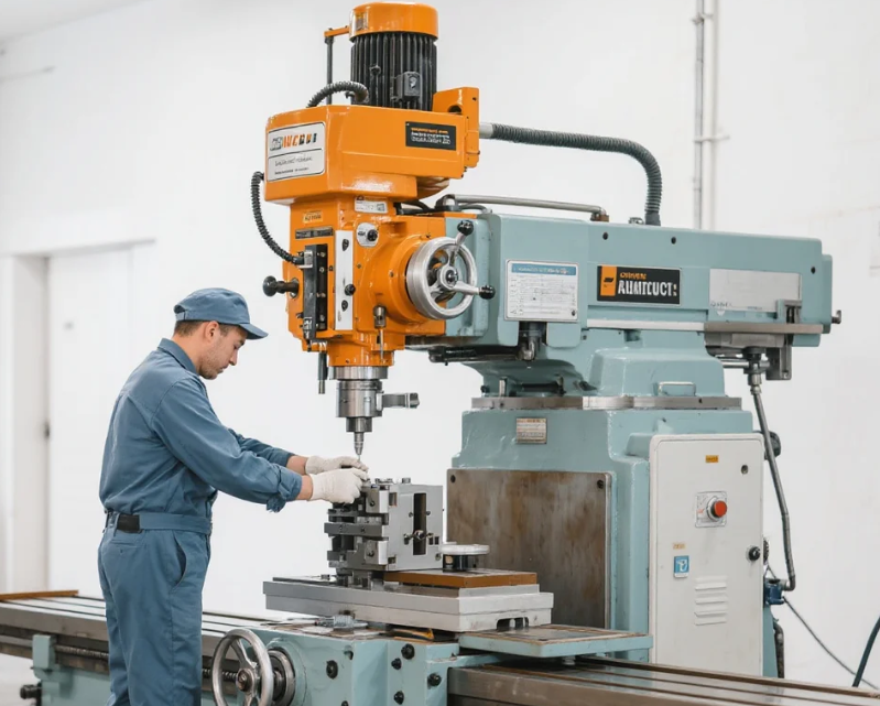
An annotated illustration labeling seven main parts of a vertical milling machine: base, column, knee, saddle, worktable, spindle, and control panel—offering a concise visual guide.
First Diagram (Top-Left)
This is a classic column-and-knee milling machine schematic. It clearly labels essential parts such as the base, column, knee, saddle, table, overhanging arm, and spindle—all arranged in the standard layout for this versatile design.
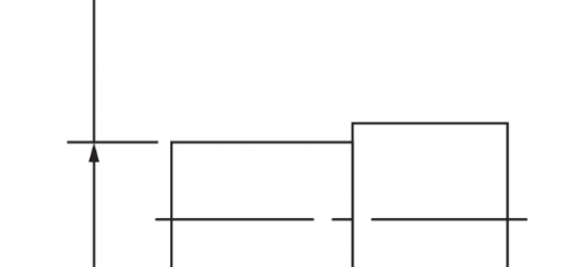
Second Diagram (Top-Right)
A stylized rendering featuring a similar setup: base, knee, saddle, table, and column with guideways. Ideal for quickly grasping how parts align and move in the machine.
Third Diagram (Bottom-Left)
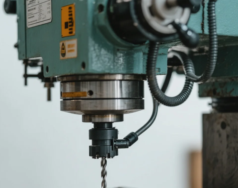
This diagram zooms in on structure and mechanics of a vertical milling machine. It highlights the spindle, handles/controls, and table—helpful for understanding motion and operator interaction.
Milling Machine Components
A milling machine is a versatile machine tool used to remove material from a workpiece using rotary cutters. Here are its main components:
- Base
The foundation of the machine; provides stability and supports the entire structure. Usually made of cast iron for rigidity and vibration absorption. - Column
Mounted on the base, it houses the spindle, motor, and other driving mechanisms. Provides vertical support for the milling head. - Knee
A vertically adjustable part mounted on the column. Supports the saddle and table, allowing vertical movement (Z-axis). - Saddle
Mounted on the knee, it allows horizontal movement of the table (Y-axis). - Table
The work-holding surface of the machine. Provides longitudinal movement (X-axis) and supports vices, fixtures, or workpieces. - Spindle
Rotates the cutting tool. Powered by an electric motor via gears or belt drive. - Overarm (Arbor Support) (for horizontal milling)
Supports the arbor and cutting tool to prevent deflection. - Arbor (Horizontal milling machines)
A shaft that holds the cutter. - Milling Head (or Ram in Vertical Mills)
Houses the spindle in vertical milling machines. Can be adjusted and tilted for angular cuts. - Power Feed Mechanisms
Controls automatic movement of the table, saddle, and knee for precision milling. - Control Panel
Used to operate spindle speed, feed rate, and machine functions.
Classification of Milling Machine
Milling machines can be classified based on their construction, orientation, and functionality. Here’s an overview of the main classifications:
- Based on Orientation of Spindle
Horizontal Milling Machine
The spindle is mounted horizontally. Suitable for heavy-duty work and high material removal rates. Uses arbor-mounted cutters for large surface machining.
Vertical Milling Machine
The spindle is mounted vertically. Common for precision work and contouring. Can perform drilling, slotting, and die-sinking operations. - Based on Structure and Design
Column and Knee Type Milling Machine
Features a column supporting the spindle and a knee supporting the table. Widely used in workshops for general-purpose milling.
Examples: Plain, Universal, and Vertical Knee-Type Machines.
Fixed Bed or Manufacturing Type Milling Machine
Table moves only longitudinally, while the spindle can move vertically. Provides higher rigidity and is used for mass production.
Planer Type Milling Machine
Resembles a planer machine but has a spindle that moves along a cross rail. Used for machining large workpieces.
Plano-Miller
Large-scale machine designed for heavy-duty work. Can machine multiple surfaces simultaneously. - Based on Purpose/Function
Plain Milling Machine
Simple operations with horizontal spindle.
Universal Milling Machine
Has an additional table swivel for helical and angular milling.
Special Purpose Milling Machines
Designed for specific operations like gear milling, rotary table milling, thread milling, etc.
CNC Milling Machine
Computer-controlled, high-precision milling machine capable of complex operations.
Column and Knee Type Milling Machine
A Column and Knee Type Milling Machine is one of the most common and versatile types of milling machines used in manufacturing. It gets its name from its two main parts: the column and the knee. This type of machine is primarily designed for machining flat surfaces but can also handle slots, grooves, gears, and other complex shapes with different attachments.
- Main Components of a Column and Knee Type Milling Machine
Base – The foundation of the machine; supports the column and absorbs vibrations.
Column – The vertical structure fixed on the base; houses the spindle, motor, and driving mechanisms.
Knee – Mounted on the front of the column; supports the saddle and table, allowing vertical movement.
Saddle – Mounted on the knee; provides cross (in-and-out) movement of the table.
Table – Rectangular work surface mounted on the saddle; holds the workpiece and provides longitudinal movement.
Spindle – Rotating component that holds and drives the cutting tool.
Overarm/Overhanging Arm (in horizontal mills) – Provides support for the arbor.
Arbor/Tool Holder – Holds the milling cutter.
Feed Mechanism – Provides controlled motion of the worktable for precision machining. - Types of Column and Knee Type Milling Machines
Horizontal Milling Machine – Spindle is horizontal; suitable for heavy cutting and gear cutting.
Vertical Milling Machine – Spindle is vertical; ideal for slotting, drilling, and facing operations.
Universal Milling Machine – Features a swiveling table for angular cuts and helical milling.
Plain Milling Machine – Basic horizontal design for general-purpose milling. - Applications
Slotting, keyway cutting, and gear machining
Surface finishing of metal parts
Angular and helical milling (with attachments)
Prototyping and small to medium production runs